Write your own I²C library 
I was learning to build a drone recently, which requires me to know how to use I²C protocol. I decided to write my experience down and hope it can help others.
I used this library to read the data from the MPU9250 and built a Kalman filter to get a more reliable reading. I will write that down later. The code for the I²C library could be found on GitHub .
A brief introduction to I²C protocol 
I²C stands for Inter-Integrated Circuit, which is invented by Philips Semiconductor in 1982. It uses two bidirectional open-drain lines and requires the pull-up resistor: Serial Data line (SDA) and Serial Clock Line (SCL). An open-drain line means it can only drive the line low or be in high impedance. When the lines are idle, they are in high voltage due to the pull-up resistor.
An I²C device usually have a 7-bit address, but some devices have 10-bit address. One feature of I²C bus is that it supports multi-master mode and master-slave switch.
Typically, I²C bus works in the following transmission modes:
-
Master Transmitter Mode
-
Master Receiver Mode
-
Slave Receiver Mode
-
Slave Transmitter Mode
Common I²C bus speeds are stander mode (100 Kbit/s) and low speed mode (10 Kbit/s). The latest version of I²C bus supports fast mode (400 Kbit/s) and high speed mode (3.4 Mbit/s).
The implementation of I²C bus is generally harder than UART and SPI, fortunately, most chips hide the complexity for us which let we program towards registers . There are many libraries in the internet, however, writing our own libraries leads to a better understanding of the I²C bus.
Transferring Bits 
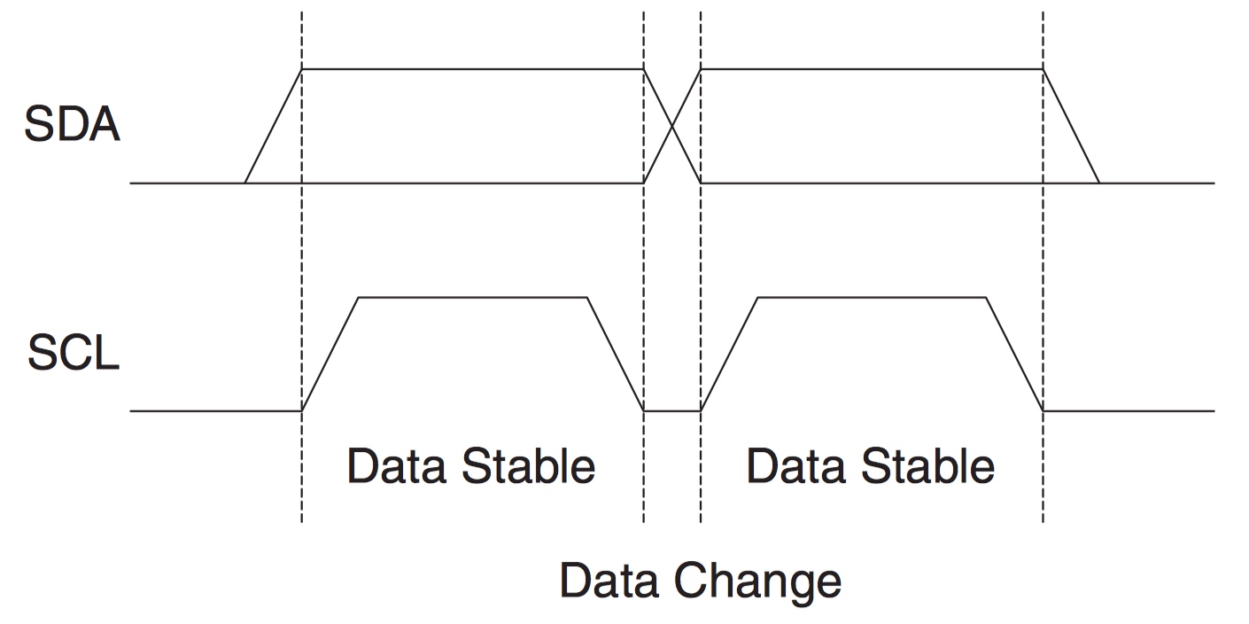
Figure 1 Data Validity, taken from ATMEL 8-BIT MICROCONTROLLER WITH 4/8/16/32KBYTES IN-SYSTEM PROGRAMMABLE FLASH DATASHEET 
As shown above, the SDA line has to remain stable when the SCL line is high, unless the signal is a START condition or a STOP condition: the chip changes the voltage level of the SDA line when the SCL line is high. Each package is 8-bit long and the MSB bit is transmitted first.
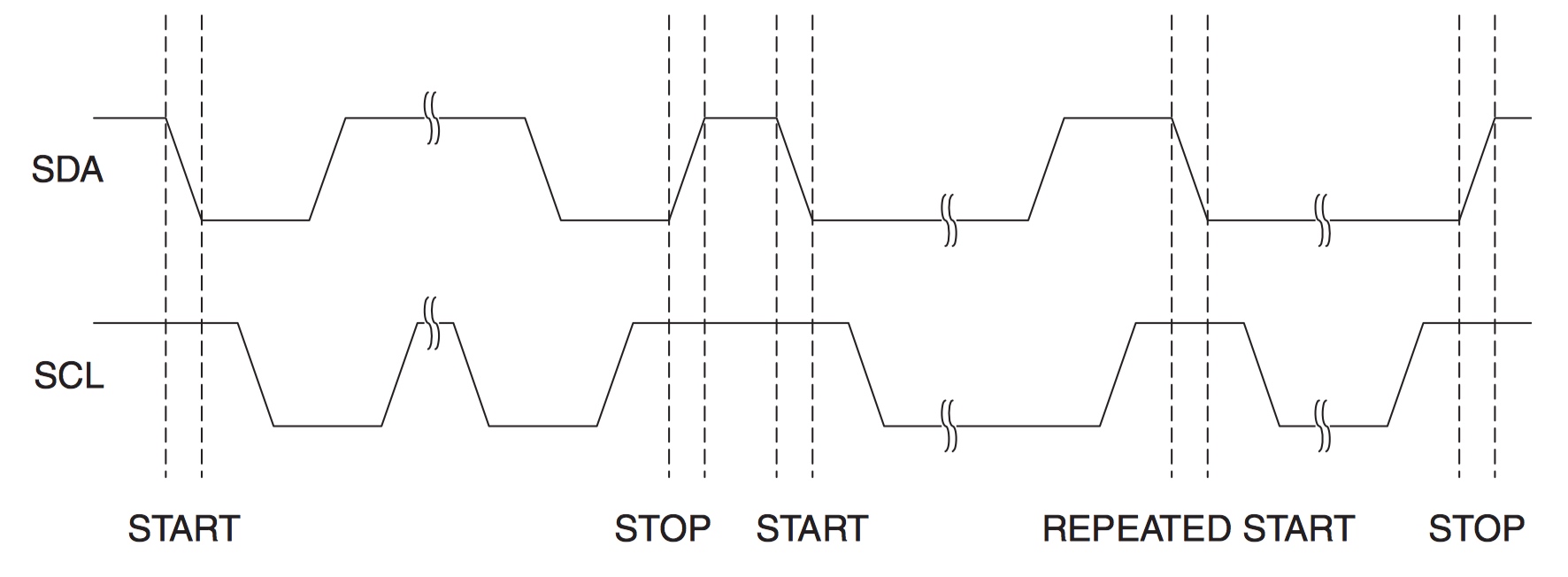
Figure 2 START, REPEATED START and STOP conditions, taken from ATMEL 8-BIT MICROCONTROLLER WITH 4/8/16/32KBYTES IN-SYSTEM PROGRAMMABLE FLASH DATASHEET 
Only the master has the authority to start or stop a transmission. The line is busy after a START signal and the no other masters should try to talk over the bus. One special condition is that between a START and STOP signal, the master can issue another START signal (repeat START), which allows it to start a new communication to the same slave without losing control of the bus.
Address Packet Format 
The I²C interface of the ATmega328P has 7-bit address. The first 7-bit of the package is for the address and the last bit is for READ/WRITE (READ is 0 and WRITE is 1). When the slave receives a package contains its address, it should pull the SCL line high at the 9th clock, which is referred as a ACK signal. Otherwise, it’s a NACK signal and the master should stop the communication or send a repeat START signal.
Usually, developers could allocate the address for the I²C device, but the address 0000 000 is reserved for a general call, which is used when a master wants to talk to all devices. If a general call is issued, salves can decide whether to respond to it.
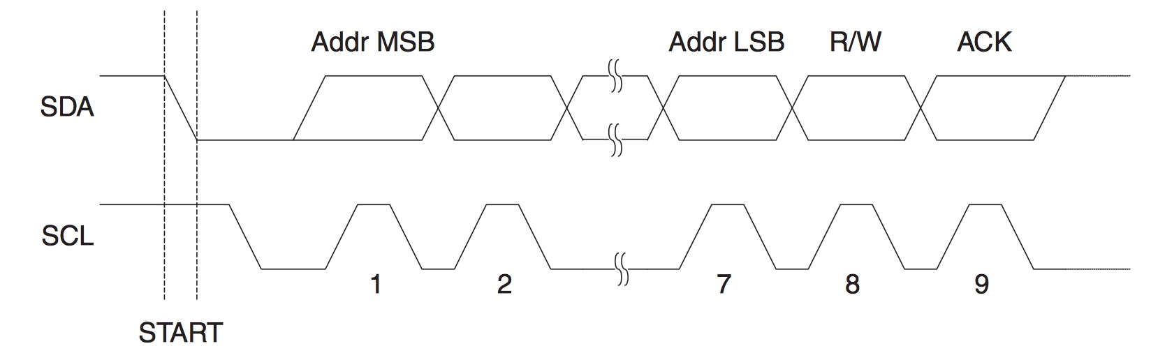
Figure 3 Address Packet Format, taken from ATMEL 8-BIT MICROCONTROLLER WITH 4/8/16/32KBYTES IN-SYSTEM PROGRAMMABLE FLASH DATASHEET 
Data Packet Format 
After receiving the 8-bit data package from a master, the slave has to generate an Acknowledge signal by pulling the SCL line low at the ninth clock. If the slave could not process more packages, it should leave the SCL line high at the ninth clock: a NACK signal.
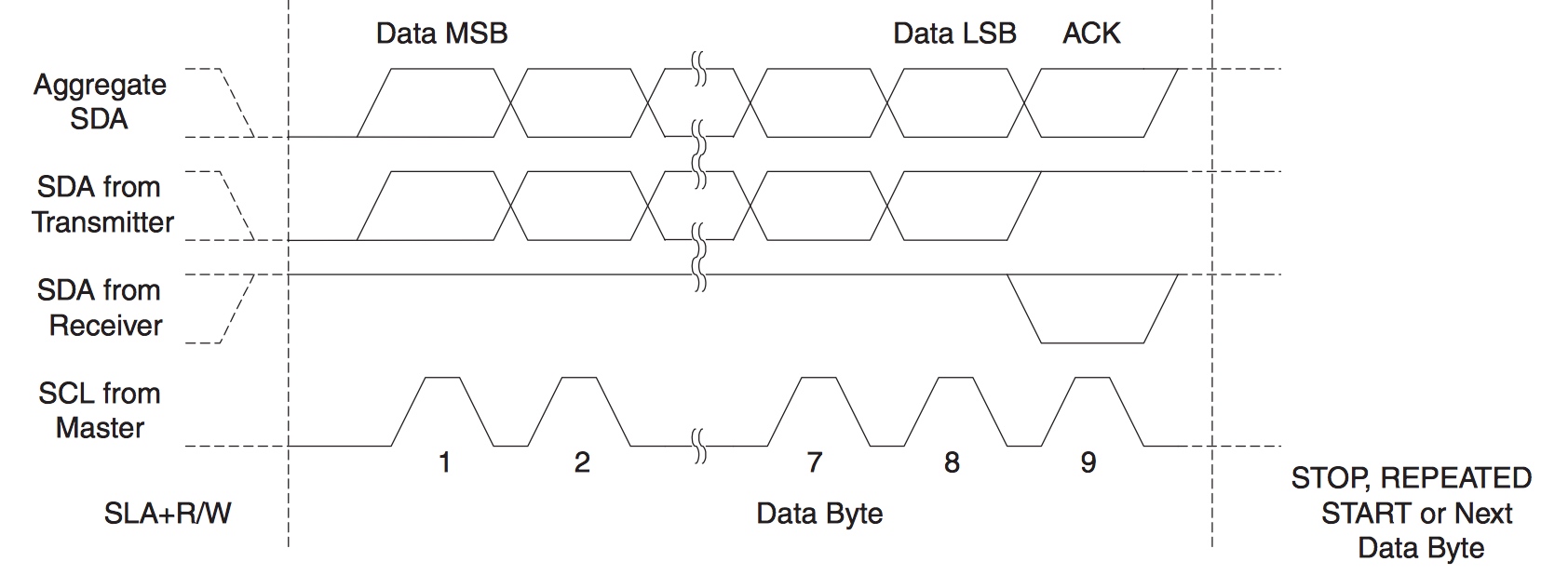
Figure 4 Data Packet Format, taken from ATMEL 8-BIT MICROCONTROLLER WITH 4/8/16/32KBYTES IN-SYSTEM PROGRAMMABLE FLASH DATASHEET 
Common transmission 
A common transmission consist of a START signal, address bits and a WRITE/READ bit, one or more data package and a STOP signal. An empty message contains only a START signal and a STOP signal is illegal. In one transmission, the slave could pull the SCL line low if it needs more time to process the data.
For convenience, we will use the following abbreviations:
-
S - START signal
-
AD - address bits
-
W - WRITE
-
R - READ
-
ACK - acknowledge bit
-
RA - register address
-
DATA - data package
-
P - STOP signal
-
NACK - not acknowledge bit
Master Transmitter mode 
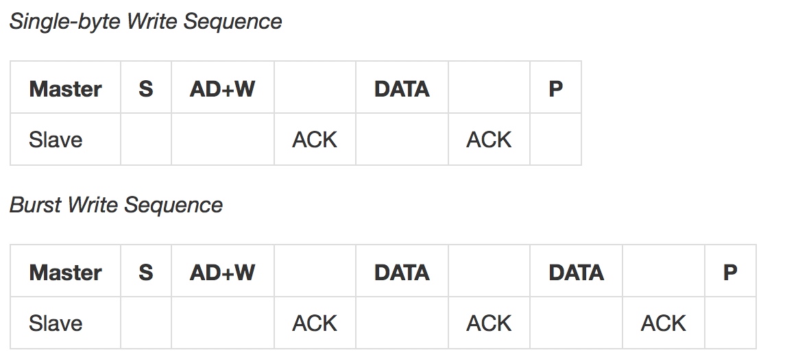
Figure 5 Master Transmitter mode 
The master sends a START signal followed by the slave address and WRITE bit. After receiving the ACK signal issued by the slave, the master starts to transmit the data packages until a STOP is singled.
Master receiver mode 
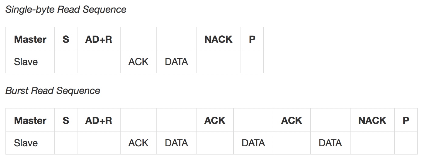
Figure 6 Master receiver mode 
After receiving the address and READ bit, the slave generates a ACK signal followed by a data package. If the master receives the data package, it has to acknowledge it to allow the slave to send more packages. The master sends a NACK signal followed by a STOP signal after receiving the last package.
Multi-master Bus Systems 
One feature of the I²C bus is the ability to have multi masters in the bus, however, it requires a mechanism to ensure that only one master takes control of the bus at a time and the synchronization of the clock generated by different masters.
Clock Synchronization 
The wired-ANDing of the I²C interface is used to synchronize the clock. Every I²C interface has two counters counting the high and low time-out periods:
-
When the SCL goes from high to low, all masters start counting the low period of the SCL line.
-
When the SCL goes from low to high, all masters start counting the high period of the SCL line.
Due to the property of the open-drain line, the SCL line is high if and only all SCL ports are high, thus the low period of the SCL line depends on the master with the longest low period, the rest masters goes to waiting mode. The first master that jumps from high to low pulls the SCL line to low, which means the high period of the SCL line equal to the high period of the master with the shortest high period.
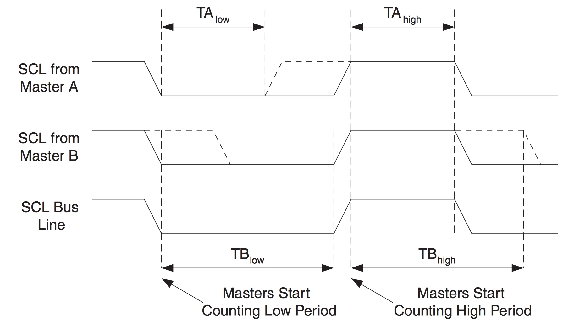
Figure 8 wired-ANDing, taken from ATMEL 8-BIT MICROCONTROLLER WITH 4/8/16/32KBYTES IN-SYSTEM PROGRAMMABLE FLASH DATASHEET 
Arbitration 
Arbitration decides which master should take control of the I²C bus.
When a master sends a data package, it continuously monitors the SDA line to see whether data is the same as what it transmitted. If it’s different, it has lost the arbitration and then becomes a slave (if it is allowed) to check whether it’s being addressed. Only when a bit in the data package transmitted from a master is high and that bit on the bus is low, the master loses the arbitration.
Arbitration will continue until there is only one master.
Note that arbitration is not allowed between:
A REPEATED START condition and a data bit.
A STOP condition and a data bit.
A REPEATED START and a STOP condition.
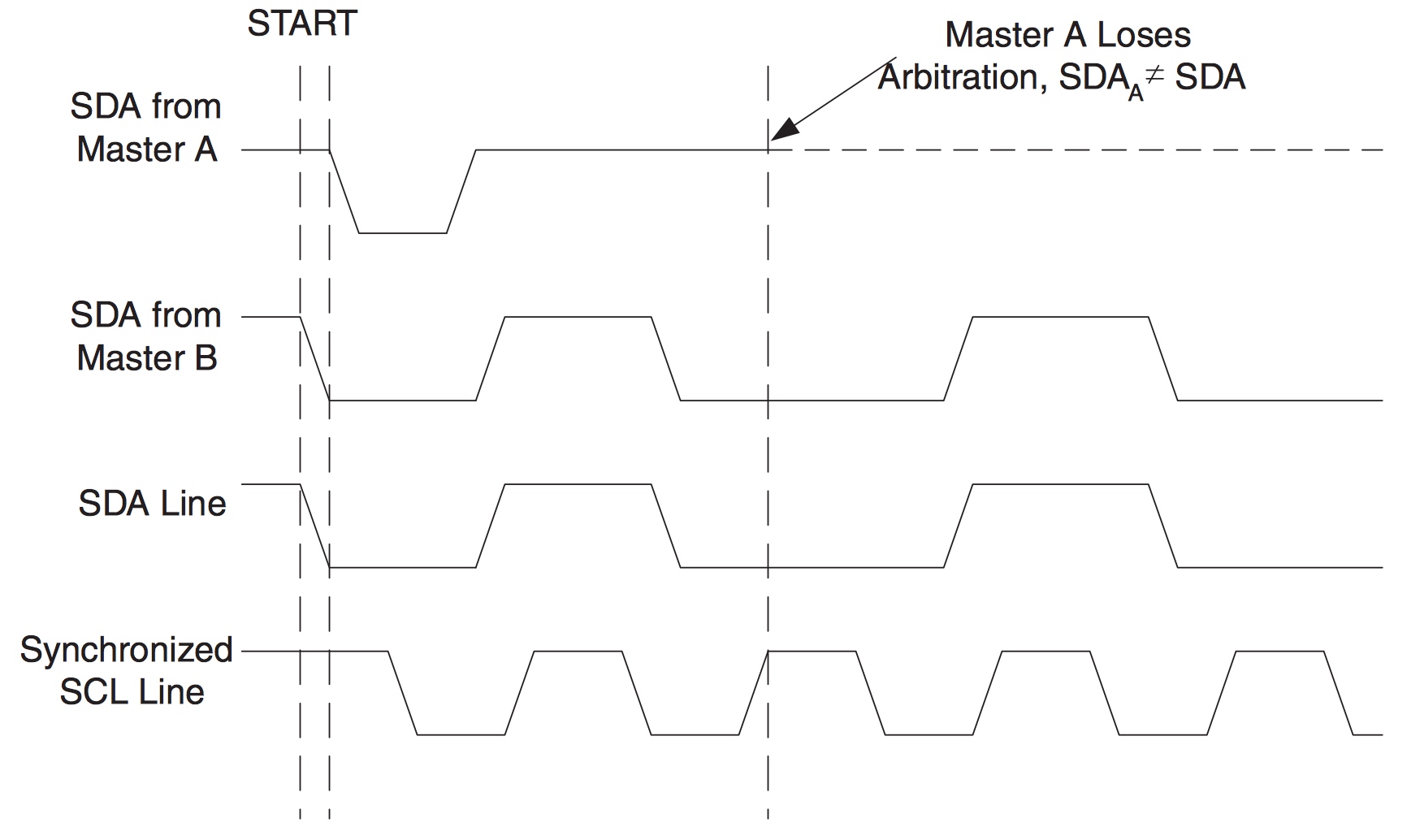
Figure 9 Arbitration, taken from ATMEL 8-BIT MICROCONTROLLER WITH 4/8/16/32KBYTES IN-SYSTEM PROGRAMMABLE FLASH DATASHEET 
ATmega328P (Arduino Nano) I²C module 
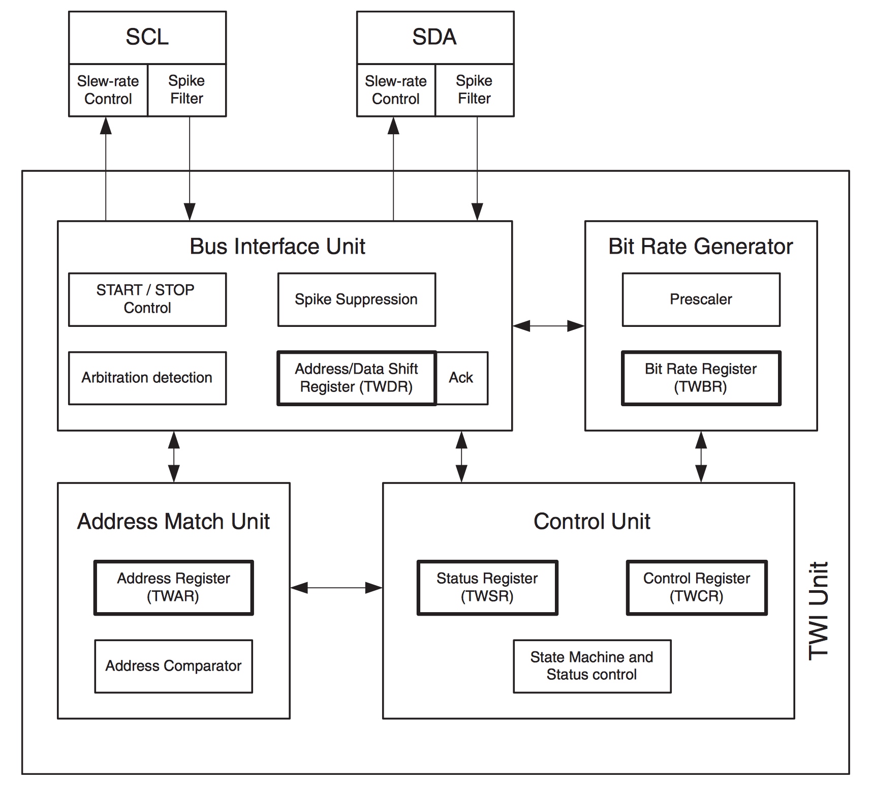
Figure 10 ATmega328P I²C Module, taken from ATMEL 8-BIT MICROCONTROLLER WITH 4/8/16/32KBYTES IN-SYSTEM PROGRAMMABLE FLASH DATASHEET 
The above shows that the ATmega328P I²C Module contains a START/STOP control unit, an Arbitration detection unit, an Address Match unit, a Bit Rate Generator and an ACK unit. Therefore, we could “program towards registers”.
When an ATmega328P serves as a master, the SCL clock frequency can be computed by:
Where
-
TWBR = the value of the TWBR register (TWI Bit Rate Register)
-
PrescalerValue = the TWPS1 and TWPS0 bits in the TWSR register (TWI Status Register)
-
CPU Clock frequency = 16 MHz for ATmega328P
When the I²C Module is working, it continuously detects the bus to see whether it loses the arbitration. The status is stored in the bit 7 to bit 3 of TWSR register.
The I²C Module is based on interrupt, after finishing one operation, the TWSR register will record the current status and the TWINT bit in the TWCR register (TWI Control Register) will be set to 0 automatically. If the TWIE bit in the TWCR and the I bit in the SREG register are set to 1, the I²C Module will issue an interrupt request. By the way, we could know whether an operation is finished by checking the value of the TWINT bit.
The TWINT Flag is set in the following situations:
After the TWI has transmitted a START/REPEATED START condition.
After the TWI has transmitted SLA+R/W.
After the TWI has transmitted an address byte.
After the TWI has lost arbitration.
After the TWI has been addressed by own slave address or general call.
After the TWI has received a data byte.
After a STOP or REPEATED START has been received while still addressed as a Slave.
When a bus error has occurred due to an illegal START or STOP condition.
Initialize the I²C module 
If we don’t want to use an external pull-up resistor, we could turn on the internal pull-up resistor:
pinMode(SDA, INPUT_PULLUP);
pinMode(SCL, INPUT_PULLUP);
Based on the SCL clock and PrescalerValue, the TWBR can be computed by:
TWBR = (CPU_freq/I2C_freq/1000-16)/2;
If we want it work as a slave, the address has to be assigned and stored in the TWAR register:
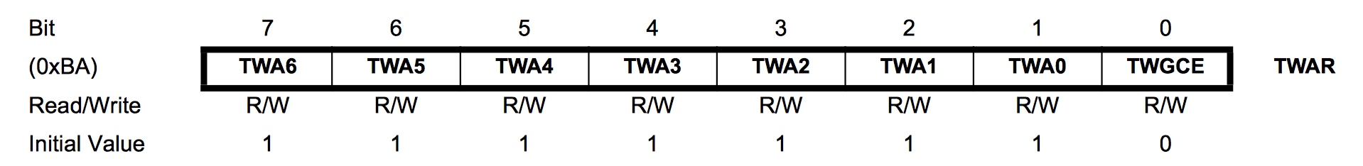
Figure 11 TWAR register, taken from ATMEL 8-BIT MICROCONTROLLER WITH 4/8/16/32KBYTES IN-SYSTEM PROGRAMMABLE FLASH DATASHEET 
The bit 7 to bit 1 is for the address. The device will respond to a general call if the bit 0 is set. Because the address is 7-bit long and a byte is 8-bit long, we could use the bit 6 to bit 0 of a byte to represent the address and shift left by 1 bit. For example, the address is 1101000, we could use #define ADDRESS 0x68(0x86 = 01101000):
#define RESPOND_GC 0x00
#define NOT_RESPOND_GC 0x01

if(generalCall)
    TWAR = (selfAddress<<1) | RESPOND_GC;
else
    TWAR = (selfAddress<<1) | NOT_RESPOND_GC;
As a slave, the I²C module has to be enabled to monitor the I²C bus by setting TWEA and TWEN bit in the TWCR register to 1. The I²C module will generate an ACK signal when needed if the TWEA bit is 1. The TWEN bit is used to enable the I²C module. We could set TWIE bit in the TWCR register to 1 to enable the interrupt:
#define _BV(bit) (1 << (bit))

TWCR = (_BV(TWEA)) | (_BV(TWEN)) | _BV(TWIE);
sei();  //enable the global interrupt
Transmit the START signal 
AS mentioned above, the I²C module contains the START and STOP control unit, which could be accessed from TWCR register:
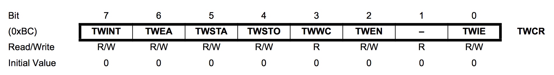
Figure 12 TWCR register, taken from ATMEL 8-BIT MICROCONTROLLER WITH 4/8/16/32KBYTES IN-SYSTEM PROGRAMMABLE FLASH DATASHEET 
When we write 1 to TWSTA bit, the I²C module will check whether the bus is idle, and transmits a START signal if it’s idle, otherwise, it goes to waiting mode unless a STOP signal is monitored. We need to write 0 to TWSTA bit if we don’t want to generate the ACK signal.
After this, the I²C module is enabled when 1 is written to TWEN bit and takes control of the SDA and SCL pin. If 0 is written to this bit, the I²C module is switched off immediately, discarding any ongoing operation.
To let the I²C module start transmitting, the I²C interrupt flag has to be cleaned by writing 1 to TWINT bit. The TWINT
bit is set automatically if an operation is complete by hardware, which means we could pull the value of TWINT bit to
know whether an operation is complete:
            while(!(TWCR


            &


            (_BV(TWINT))))
;.
After an operation, we has to read the status stored in the TWSR register to know whether an operation is successful. The status code could be found in Table 22-2, Table 22-3, Table 22-4 and Table 22-5 of ATMEL 8-BIT MICROCONTROLLER WITH 4/8/16/32KBYTES IN-SYSTEM PROGRAMMABLE FLASH DATASHEET .
#define STATUS_CODE_MASK 0xF8
#define START 0x08

TWCR = (_BV(TWINT)) | (_BV(TWSTA)) | (_BV(TWEN));
while(!(TWCR & (_BV(TWINT))));  //wait for the transmission finish
if((TWSR & STATUS_CODE_MASK) != START){
    //code to do some operations when the transmission is unsuccessful
}
Transmit a STOP signal 
The code to generate a STOP signal is simple:
TWCR = (_BV(TWINT))|(_BV(TWEN)) | (_BV(TWSTO));
while(!(TWCR & (_BV(TWSTO))));
Transmit the address and WRITE/READ bit or data 
The data is stored in TWDR register. We can only write to TWDR register when the TWINT bit is 1. And we don’t have access to the TWDR register before the first interrupt flag. When the data is ready, the TWINT and TWEN bit should be written to 1 to start transmitting.
#define MT_SLA_W_ACK 0x18
#define WRITE 0x00
#define READ 0x01

TWDR = (address<<1) | WRITE;   //or  TWDR = (address<<1) | READ;
TWCR = (_BV(TWINT)) | (_BV(TWEN));
while (!(TWCR & (_BV(TWINT))));
if((TWSR & STATUS_CODE_MASK) != MT_SLA_W_ACK){
    //code to do some operations when the transmission is unsuccessful
}
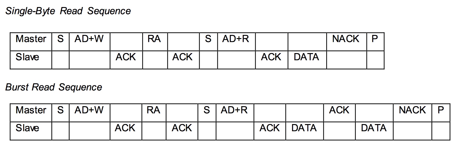
Request messages from a slave 
As mentioned above, the I²C module has three transmitter modes: Master receiver mode, Master transmitter mode and Combined transmission mode. The Combined transmission mode is a combination of Master transmitter mode and Master receiver mode, here we focus on the burst read sequence in the Master receiver mode.
The master sends a START signal to start the transmission followed by the salve address and a READ bit. We could use a for loop to read the bytes, but a NACK is issued by the master after reading the last byte. The TWEA bit is written to 1 to issue an ACK signal, otherwise a NACK signal is issued.
#define RX_BUFFER_SIZE 32
#define MR_DATA_ACK 0x50
#define MR_DATA_NACK 0x58

uint8_t rxBuffer[RX_BUFFER_SIZE];
uint8_t rxBufferIndex;
uint8_t rxBufferLength;

//initialise the buffer
rxBufferLength = num;
rxBufferIndex = 0;

//if the requested number of bytes is larger than RX_BUFFER_SIZE,
//truncate it to RX_BUFFER_SIZE
if(num>RX_BUFFER_SIZE)
    num = RX_BUFFER_SIZE;

for(uint8_t n=0;n<num-1;n++){
    TWCR = (_BV(TWEA)) | (_BV(TWINT)) | (_BV(TWEN));
    while(!(TWCR & (_BV(TWINT))));
    if((TWSR & STATUS_CODE_MASK) != MR_DATA_ACK)
        error(MR_DATA_ACK);
    rxBuffer[n] = TWDR;
}

//after reading the last byte, the I²C bus needs to generate a NACK signal
TWCR = (_BV(TWINT)) | (_BV(TWEN));
while(!(TWCR & (_BV(TWINT))));
if((TWSR & STATUS_CODE_MASK) != MR_DATA_NACK)
    error(MR_DATA_NACK);
rxBuffer[num-1] = TWDR;
The master should send a STOP signal after this.
Receive messages from a salve 
As a slave, the I²C module is initialized differently and we need to back up the TWCR register: uint8_t backup = TWCR;. Then we should check the status of the I²C module to make sure the master is calling the device. If the device is addressed, the buffer array is initialized, switch off the interrupt request ( The I²C module will generate an interrupt request every time it completes an operation if the interrupt request function isn’t switched off, and the chip will store these requests and process them after this interrupt routing ) and turn on the acknowledge generator. Usually, we put the following code in the ISR function to allow the device do other tasks while waiting for the request from a master.
#define SR_AD_RECEIVED 0x60
#define GENERAL_CALL 0x70
#define SR_PRE_AD_DATA_ACK 0x80
#define SR_PRE_GC_DATA_ACK 0x90

uint8_t status = TWSR & STATUS_CODE_MASK;
if(status == SR_AD_RECEIVED || status == GENERAL_CALL){
    TWCR = (_BV(TWINT)) | (_BV(TWEN)) | (_BV(TWEA));
    //initialize the buffer
    rxBufferIndex = 0;
    rxBufferLength = 0;
    while(!(TWCR & (_BV(TWINT))));
}
The reading code below should be put in the if statement shown above. The program jumps out from the while loop if the received byte is not a data or something goes wrong.

status = TWSR & STATUS_CODE_MASK;
while(status == SR_PRE_AD_DATA_ACK || status == SR_PRE_GC_DATA_ACK){
    rxBuffer[rxBufferIndex++] = TWDR;
    rxBufferLength++;
    TWCR = (_BV(TWINT)) | (_BV(TWEN)) | (_BV(TWEA));
    while(!(TWCR & (_BV(TWINT))));
    status = TWSR & STATUS_CODE_MASK;
}

//received a STOP signal
if(status == SR_STOP){
    rxBufferIndex = 0;
}else{
//code to do some operations when the transmission is unsuccessful
}
Don’t forget to restore the TECR register: TWCR = backup;.